We wanted Alejandro to have a power wheelchair. We wanted him to be able to move through the world by his own volition and it’s clear that the ability to independently explore his environment is important for his cognitive development on multiple levels. We tried going through the typical process of obtaining a power wheelchair but met numerous obstacles:
- A new power wheelchair was much too expensive for our family to purchase out of pocket.
- Blue Cross Blue Shield of Illinois wouldn’t pay for one because they already paid for a medical stroller when Alejandro was 9 months old. We were told that we needed to wait 5 years. This was much too long to wait, especially during these early years which are so important developmentally.
- Recent cuts to the Illinois Medicaid program have made it very difficult to obtain funding for such devices.
- Alejandro is very weak and it was difficult to find an off the shelf access method that he could use. While there are a number of sensitive switches, joysticks and sensors available none of them seemed feasible as they all required a precise and delicate positioning that would be lost the moment his wheelchair hit a bump. Furthermore, finding this positional sweet spot took too much time for practical use.
Our best option was to for me to try to build something myself.
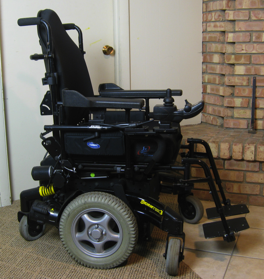
While looking for motors and wheels on Ebay I stumbled across a used adult Invacare TDX3 with MK5 electronics for relatively cheap ($800, shipping included, batteries not). I decided that starting with this was a signifiant head start on the project and was well worth the money. I purchased the wheelchair with the intention of using the motorized base and controller and then add new seating and a customized access method. I also purchased a wheelchair programmer, a device that allows you to configure and modify the wheelchair’s internal drive and control parameters.
Seating
The chair from Alejandro’s EasyS stroller fits him well and provides decent support as well as being reclinable and adjustable. It can detach from the stroller base and attach to a ‘Hi-Lo’ base for use around the house and it also allows you to attach a tray.
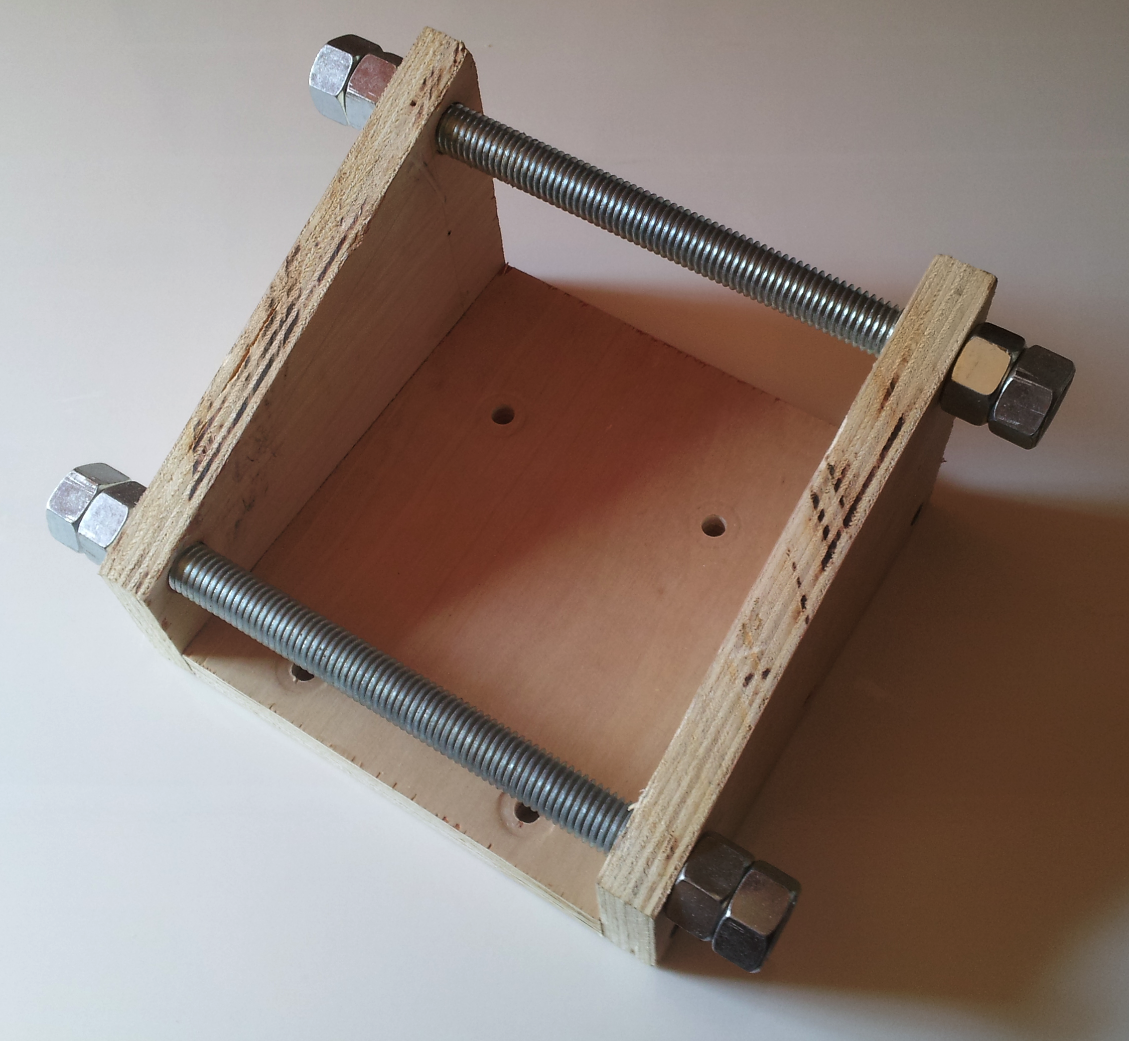
I fabricated a mating piece to be fixed to the power wheelchair base, allowing the EasyS chair to clip into it the same way it clips into the stroller base or the Hi-Lo base. Below is a photo of the piece that I built from plywood which is sturdy and adequate although at some point I’ll have someone weld up a metal version now that I have a working prototype.
Due to the adjustable and reclinable nature of the EasyS there are two sliding extruded aluminum rails that extend below and behind the seat. They protrude the most when the chair is in an upright position, which is necessary for driving. I was able to acquire a pair of shorter versions of this piece which allowed me to get the entire seat assembly as low and small as possible. I wanted the seat to be low for stability and also because I want my kid to move through the world at a height which is typical for people his age.
MK5 Interface
None of the available methods that I investigated seemed to be feasible for Alejandro to be able to consistently and reliably control a wheelchair. It was pretty clear that I’d have to come up with something myself and I would somehow have to interface this with the wheelchair electronics in order to drive it. The Invacare MK5 electronics communicate with the user controls via a proprietary serial protocol. Other’s have tried to hack this without success and I really don’t have time to try my hand at it so I decided to find a more simple route.
I originally purchased a 1554M5 Sip & Puff interface on Ebay which connects the the MK5 electronics. The 1554M5 has a mini-DIN connector for a Proportional Attendant Control and also a DB9 connector for switch inputs. The DB9 connector pinout is documented and has inputs for forward, reverse, left and right. I tested this by connecting some pushbuttons but was disappointed with its functionality. Pressing the forward button moves the chair forward at the programmed speed and pressing the left button rotates the chair in place as well. Unfortunately pressing the forward and left buttons simultaneously moves the chair in the expected direction, but at a speed which seems to be the sum of the programmed forward and turning speeds. This is a speed which is greater than both the forward and turning speeds resulting in a somewhat jerky operation when switching headings. I played with the drive parameters for quite awhile but was never able to get any reasonably smooth transition from forward to a turn. Besides this I really wanted Alejandro to have a proportional control if at all possible.
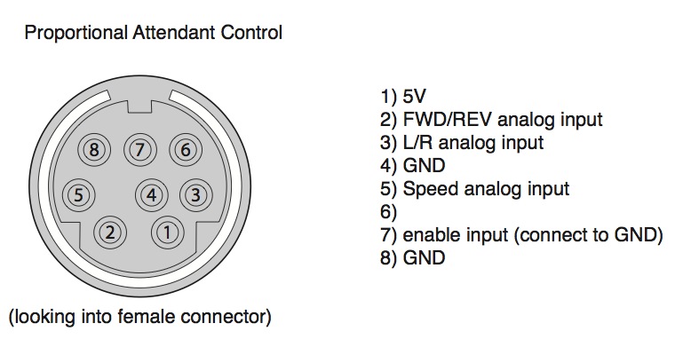
The pinout for the Proportional Attendant Control is not published but I was able to figure it out by poking around and making some educated guesses based on the documented functionality and by following circuit board traces. There are three analog inputs for X/Y and an overall speed control, as well as a switch input to override the user control and enable the attendant control. Unfortunately the the MK5 electronics do not allow you to provide drive profile settings for the attendant control. There are no adjustments for acceleration, braking, torque etc., these are all set at some pre-programmed values. I wanted to be able to program different drive profiles for indoor, outdoor, learning etc., so my search continued.
What I finally settled on was a modified Invacare 1812 Joystick. The 1812 is a proportional (analog) joystick which connects to the MK5 electronics and can be assigned to the drive profile(s) of your choice. The 1812 contains an analog joystick and a round circuit board which measures the joystick X/Y voltages and transmits them via proprietary serial protocol to the MK5 electronics. The analog joystick outputs voltages that vary between 0V and 5V, where 2.5V is the center of each axis. I found that the 1812 that I purchased had very poor sensitivity and linearity in the left direction, even after performing a joystick throw calibration. I initially thought that I had received a broken unit so I got another one, but the second unit that I received exhibited the exact same behavior. I’m pretty sure that there isn’t a problem with the MK5 electronics or the wheelchair motors as the MPJ joystick that came with the wheelchair drives with great linearity in all directions. At this point I’m chalking it up to a firmware bug in either the 1812 or the MK5 electronics. I was able to work around this by exchanging the X and Y axes in the drive profile. This moves the poor sensitivity/linearity from the left to the reverse direction which is much less of an issue as I’m primarily concerned with steering symmetry and poor sensitivity in the reverse direction can be compensated for by adjusting the reverse speed in the drive profile.
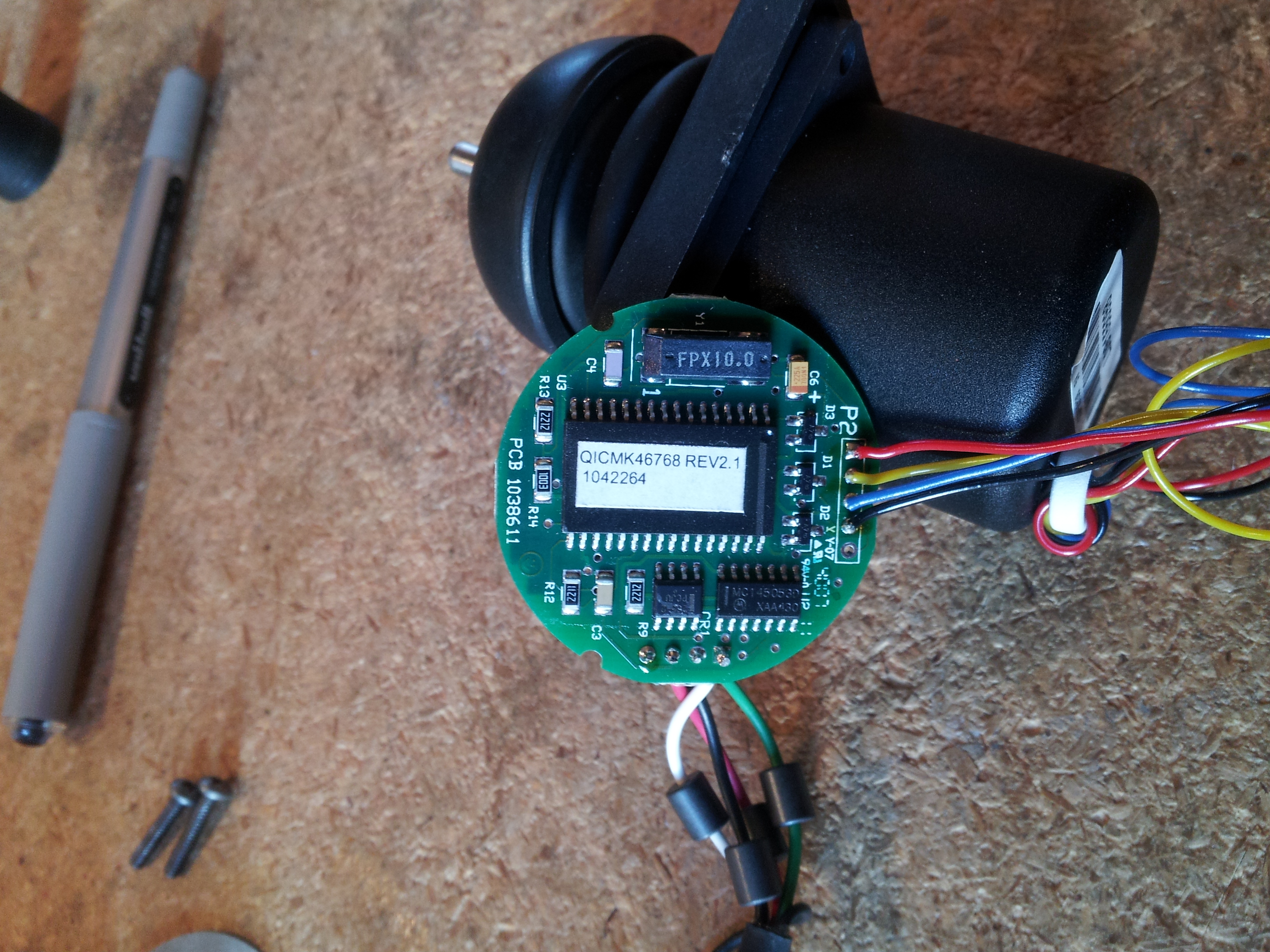
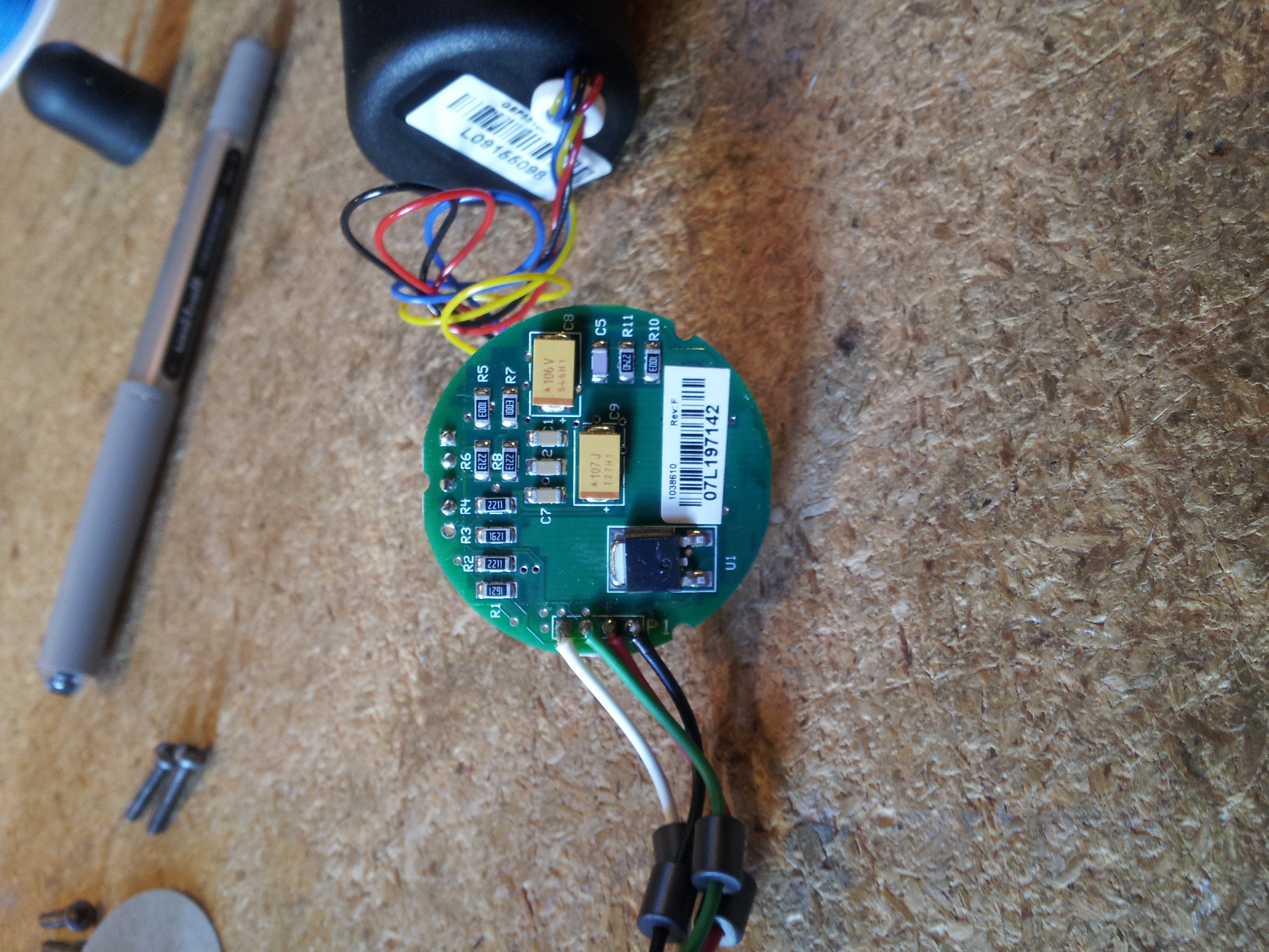
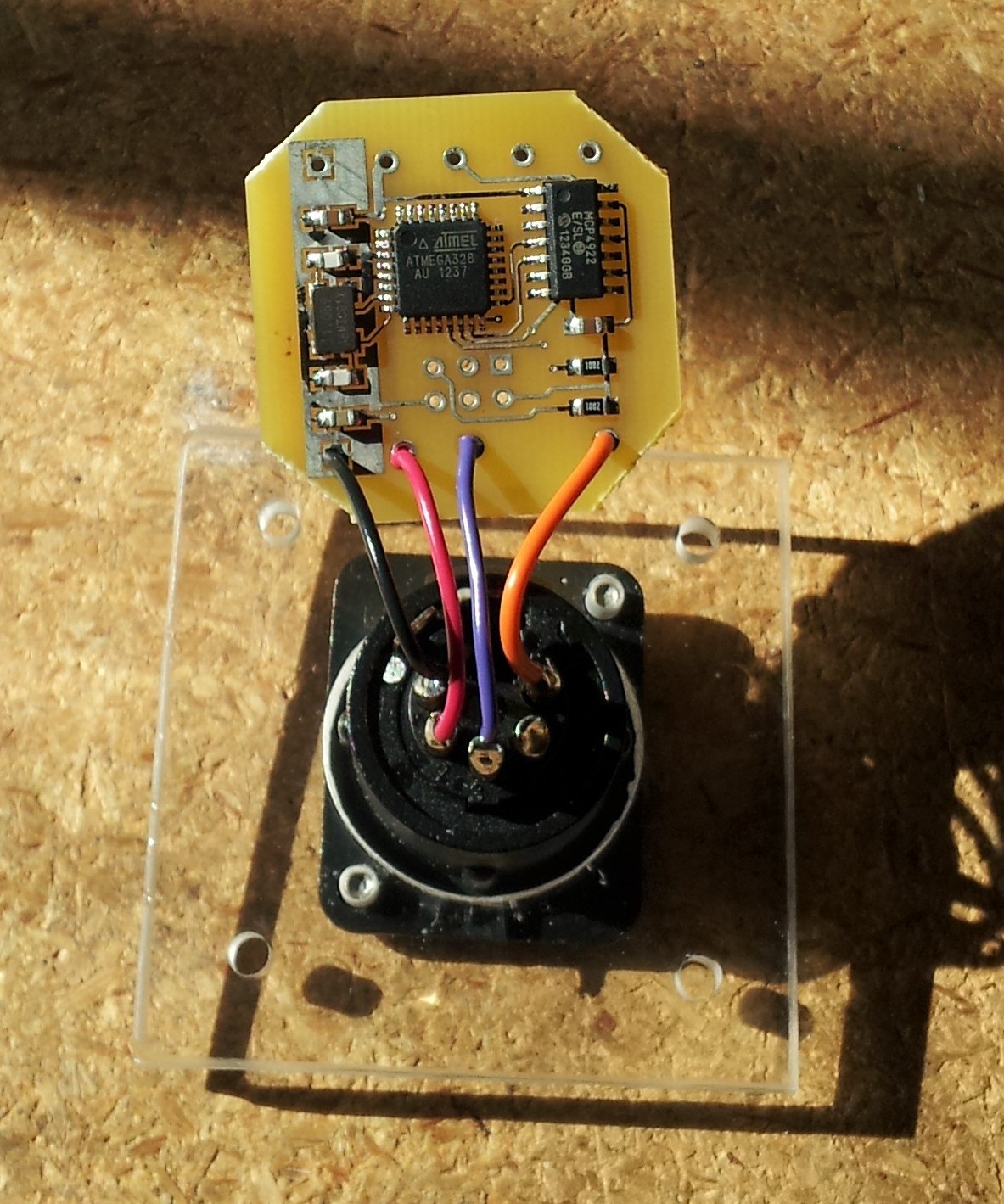
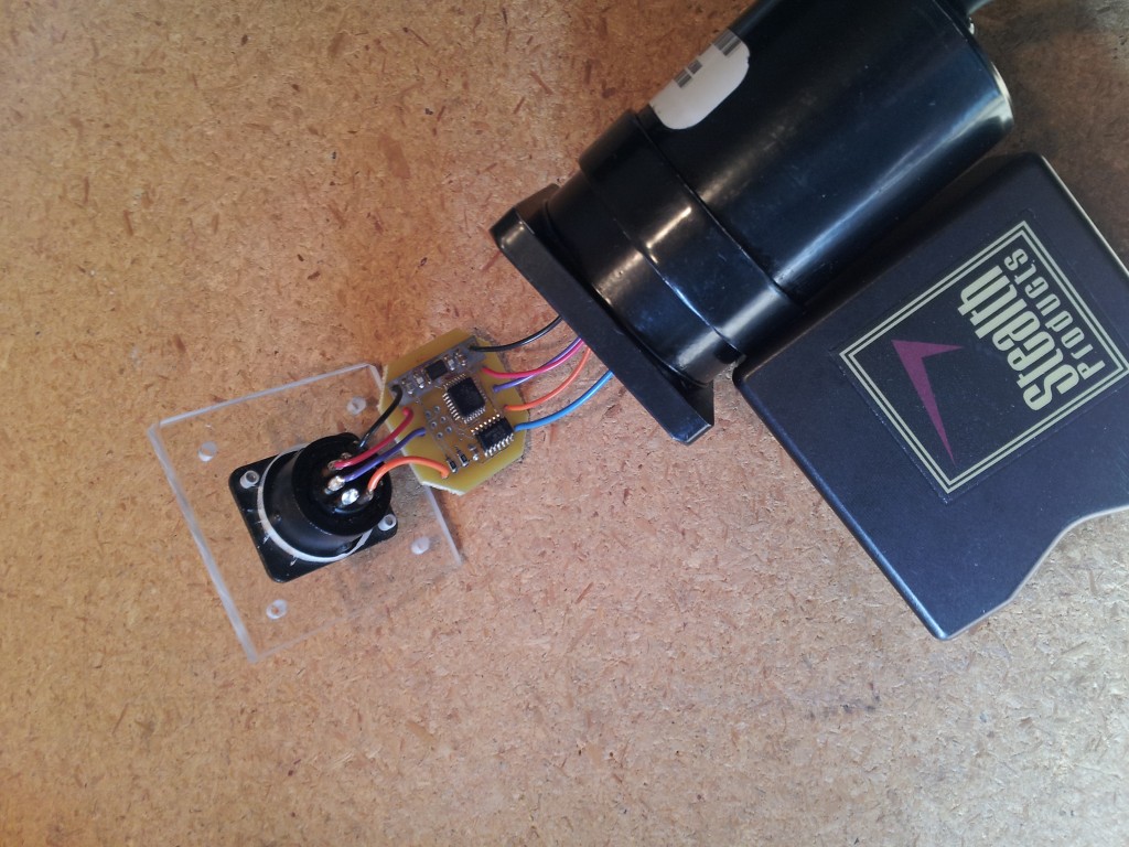
I modified the 1812 module by replacing the analog joystick with a small circuit board that I designed which simulates its output. The circuit board uses a microcontroller and D/A converter to receive serial data packets and converts them to analog X/Y voltages. These voltages are fed to the 1812 electronics where they are converted back to digital and sent to the MK5 controller. This works great and allows me to send proportional drive commands to the wheelchair without having to deal Invacare’s proprietary protocol.
I call my 1812 adapter board SERDAC (serial D/A converter). The firmware expects to see a serial X/Y data packet every 100ms or faster. If 100ms passes without the receipt of a valid packet the SERDAC immediately outputs neutral X/Y voltages (2.5V) which stops the wheelchair. This could happen if the control data source malfunctions or if the serial data cable becomes disconnected. The SERDAC will continue to output neutral X/Y voltages until it has received valid control data for a full two seconds. The last thing I want is a runaway wheelchair.
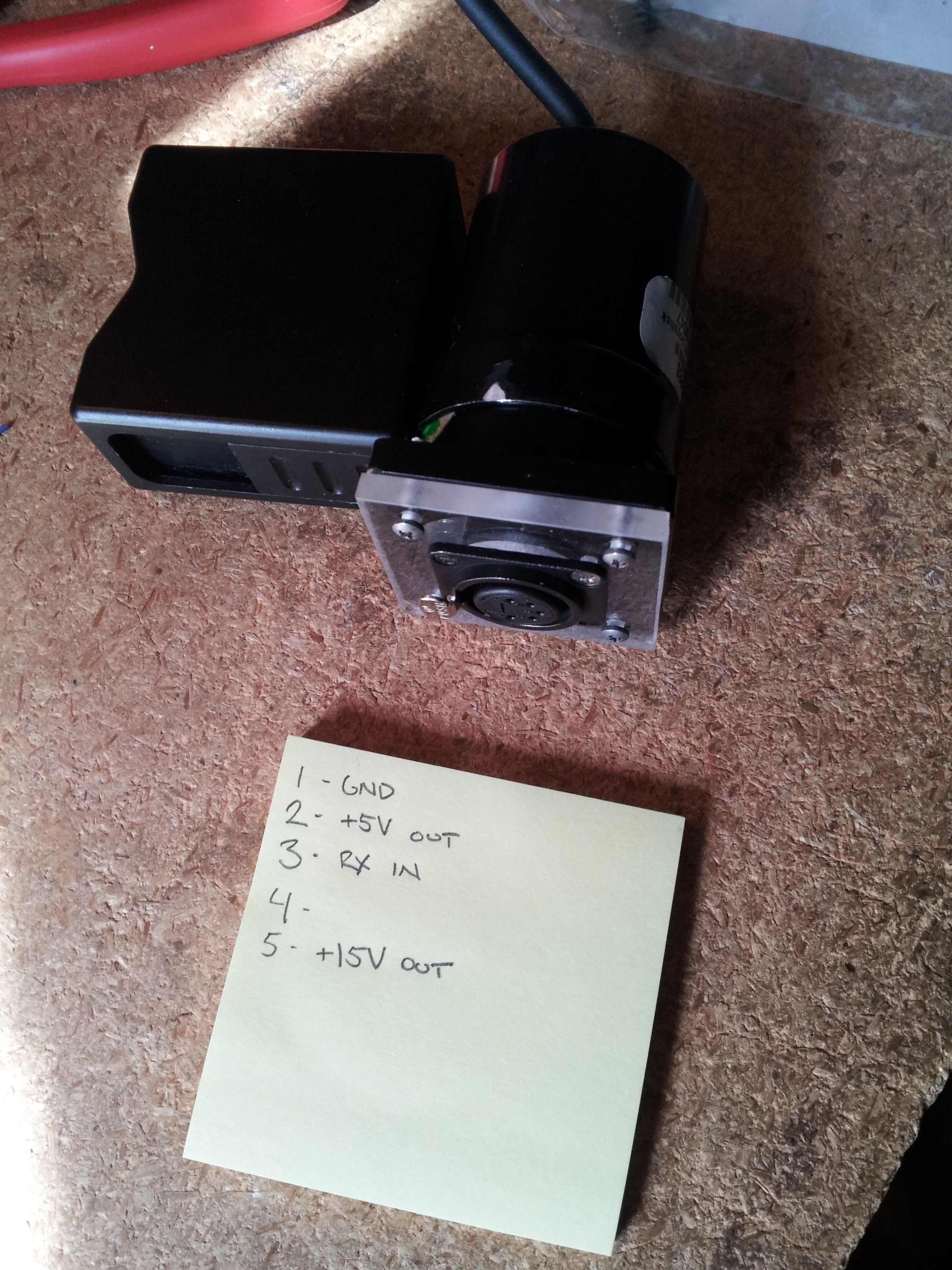
In place of the joystick I mounted a 5-pin XLR connector on the 1812 module which connects GND, serial RX and also passes along 15V power from the wheelchair for the controller and regulated 5V from the 1812 PCB.
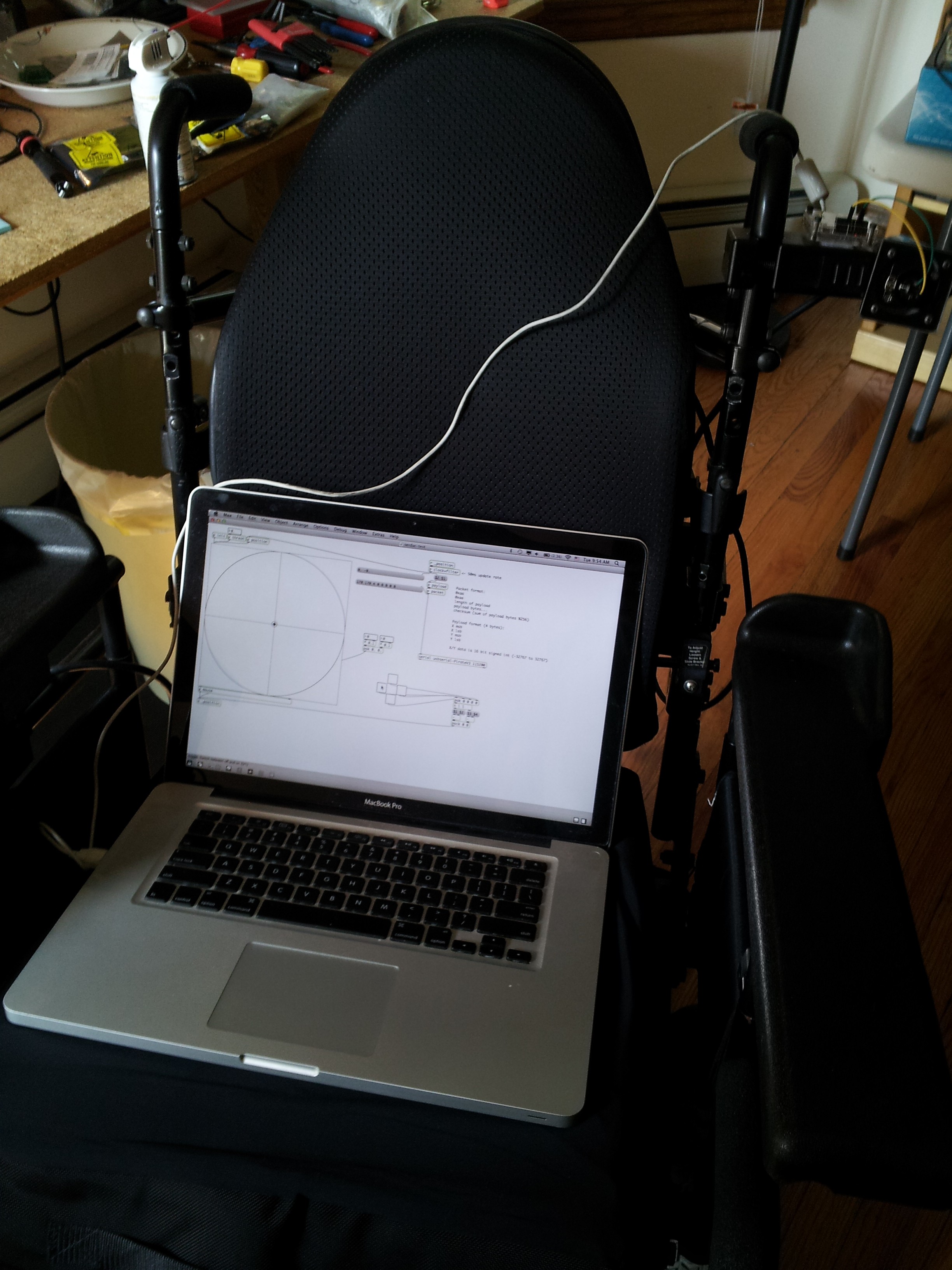
To test it all out I wrote a simple Max patch to convert mouse movements to X/Y serial data packets and used a Bus Pirate to interface my laptop to the modified 1812 joystick module. Success! The serdac schematic and source code can be downloaded here.
Access
At the time of this writing Alejandro is able to move his left index finger, his right thumb and some toes on both feet, all with very little force. About six months ago he had the opportunity to demo a power wheelchair. At that point in time his right big toe was relatively strong and he was able to deflect a small, snesitive, very carefully placed joystick in both the up and down directions. His movement was essentially planar but we had hopes that he might somehow learn to also move the joystick left and right too. As it turned out, a couple of weeks later, over the course of a couple of days he suddenly lost the ability to move that toe at all. Such is the progression of a degenerative neuromuscular condition.
We’ve always hoped that Alejandro would somehow be able to drive a wheelchair with a proportional access method. It’s clear that this allows much greater control and maneuverability. It’s difficult to find proportional access methods for people who are only able to perform planar movement and it seems generally accepted that in these cases switched access is the only option. Nevertheless I was determined to do my best to find a proportional access method that he could use. Alejandro’s toes, while quite weak, seem to respond faster to his motor intentions than his two working fingers, so I decided to focus my efforts there.
I was reminded of how tracked vehicles like tanks and bulldozers are driven. In the simplest form there are two levers, each which control the speed and direction of the associated track. The vehicle is driven using these two controls and can go forward, reverse, turn or even rotate in place. I planned to emulate some variation of this method of operation using variable amounts of force applied with Alejandro’s toes.
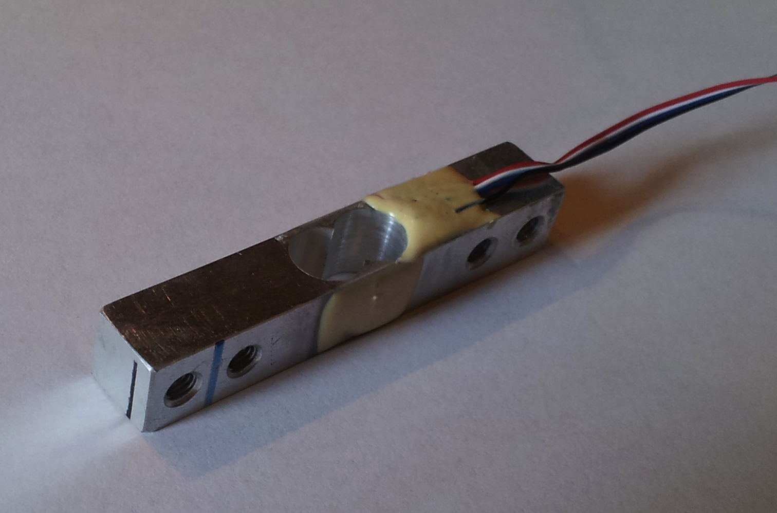
We have a digital kitchen scale which we use primarily to weigh out Alejandro’s feeding formula. About the time that I was thinking about all of this the scale broke. I decided to take it apart to see if I could fix it, which I couldn’t, but it gave me an idea. An electronic scale contains something called a ‘load cell’. This is a machined aluminum bar which is supported at one end and has a pair of strain gages epoxied to it. Placing items on the scale applies force to the unsupported end of the load cell and causes the bar to bend by a microscopic amount. When the bar bends the strain gages stretch and compress which modulates their resistances. Using a wheatstone bridge and high gain amplifier a voltage can be generated which is proportional to the amount of force applied. With the appropriate load cell and amplifier even fractions of a gram of force can be easily measured.
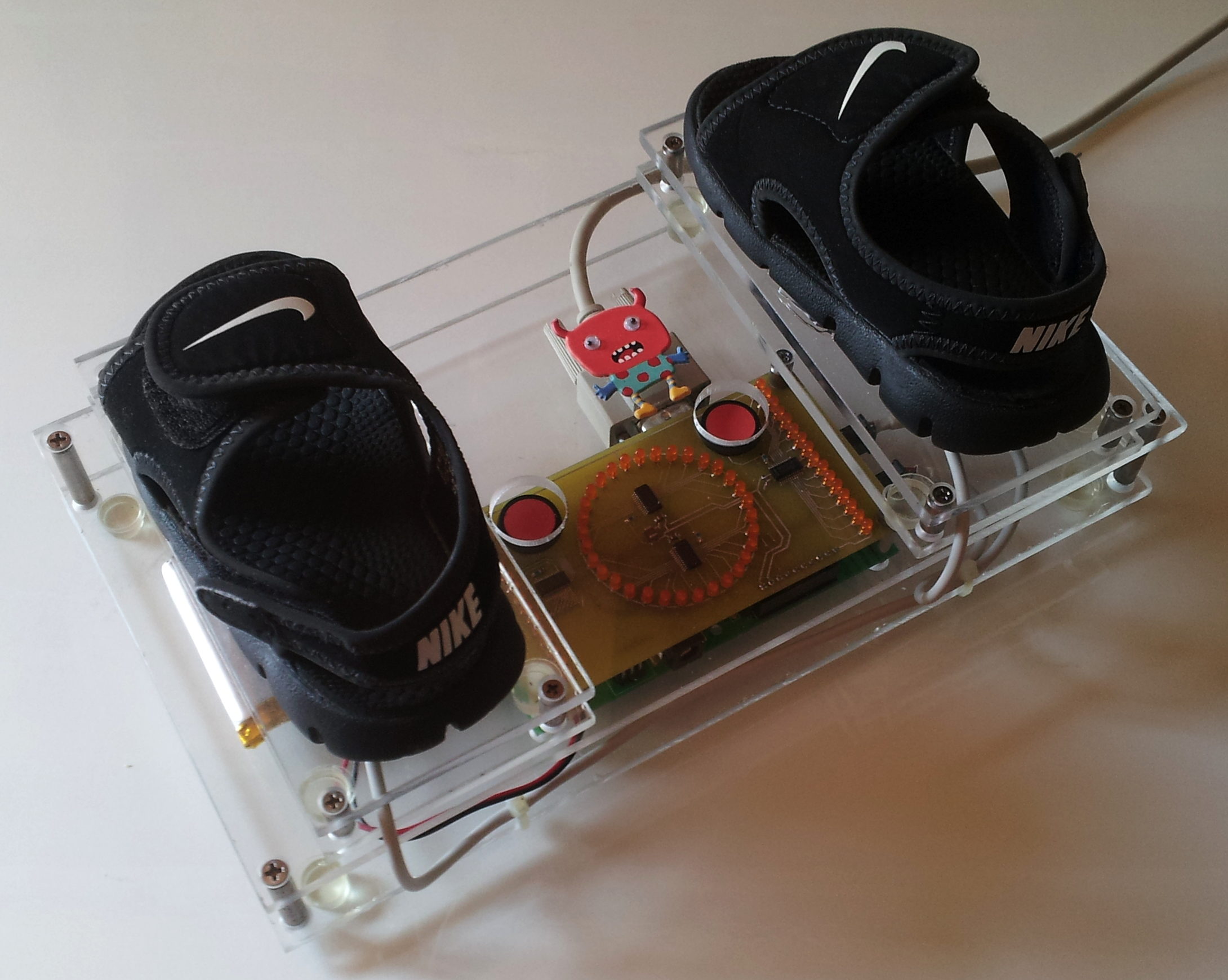
I thought that a load cell and amplifier might be a good way to measure the small amounts of force that Alejandro is able to willfully apply with his toes. I took the load cell out of our broken kitchen scale and began experimenting with it. The results were good. The next challenge was to find some way to easily and repeatably position his toes to press on the sensor. What I came up with are a pair of sensor pedals that his feet strap into, pictured below.
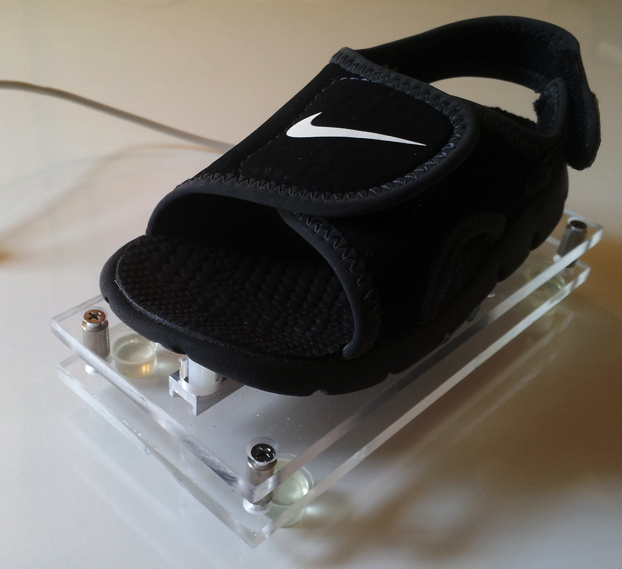
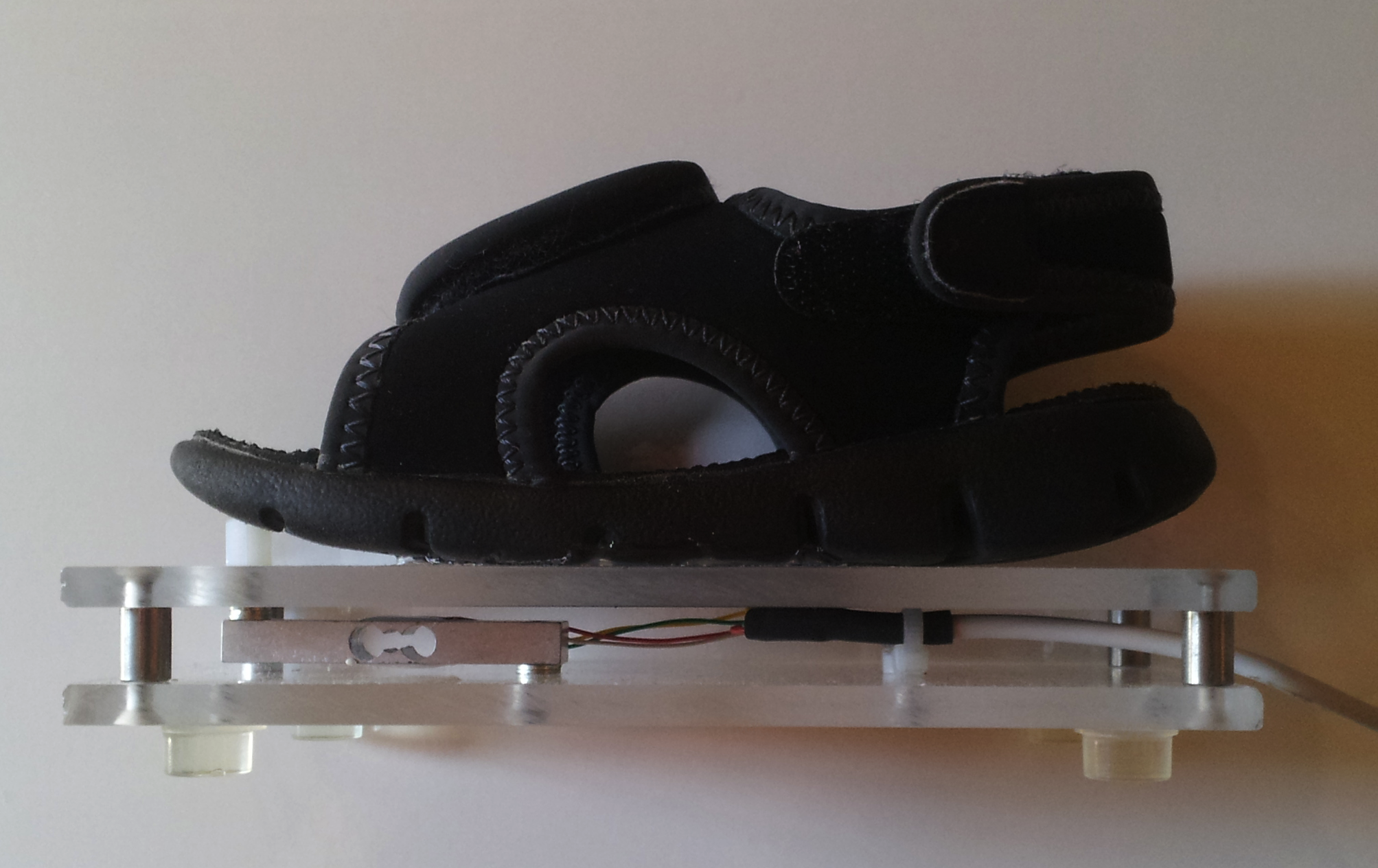
I built the pedals by gluing a pair of sandals to platforms made of plexiglass. The top level of the platform supports the bulk of the sandal and the bottom level supports one end of a load cell. The unsupported end of the load cell has a nylon standoff attached to it which protrudes through a hole in the top level of the platform and makes physical contact with the toe of the sandal. The nylon standoff was filed down to be the precise length necessary. When force is applied to the toe of the sandal it causes the load cell to flex by a measurable yet visually imperceptible amount.
Now that I had a pair of pressure sensitive pedals that Alejandro could operate I had to somehow connect them via serial interface to the power wheelchair so that he could drive it. While I was at it I also wanted to have the option of using these same pedals to control a computer via HID protocols. I designed a circuit board which includes the load cell amplifiers, a microcontroller with A/D converters, bluetooth and USB interfaces, and power supply with support for rechargeable battery powered operation.
The controller PCB also includes a 3 axis accelerometer. The pedals are very sensitive and are capable of moving the wheelchair with only a few grams of force. I was concerned that driving the wheelchair on bumpy surfaces could potentially cause unwanted forces to be applied to the pedals creating oscillations and instability in the system. The accelerometer was included to to offer the possibility of applying an intelligent damping algorithm to prevent this. At the time of this writing this has not been implemented or necessary.
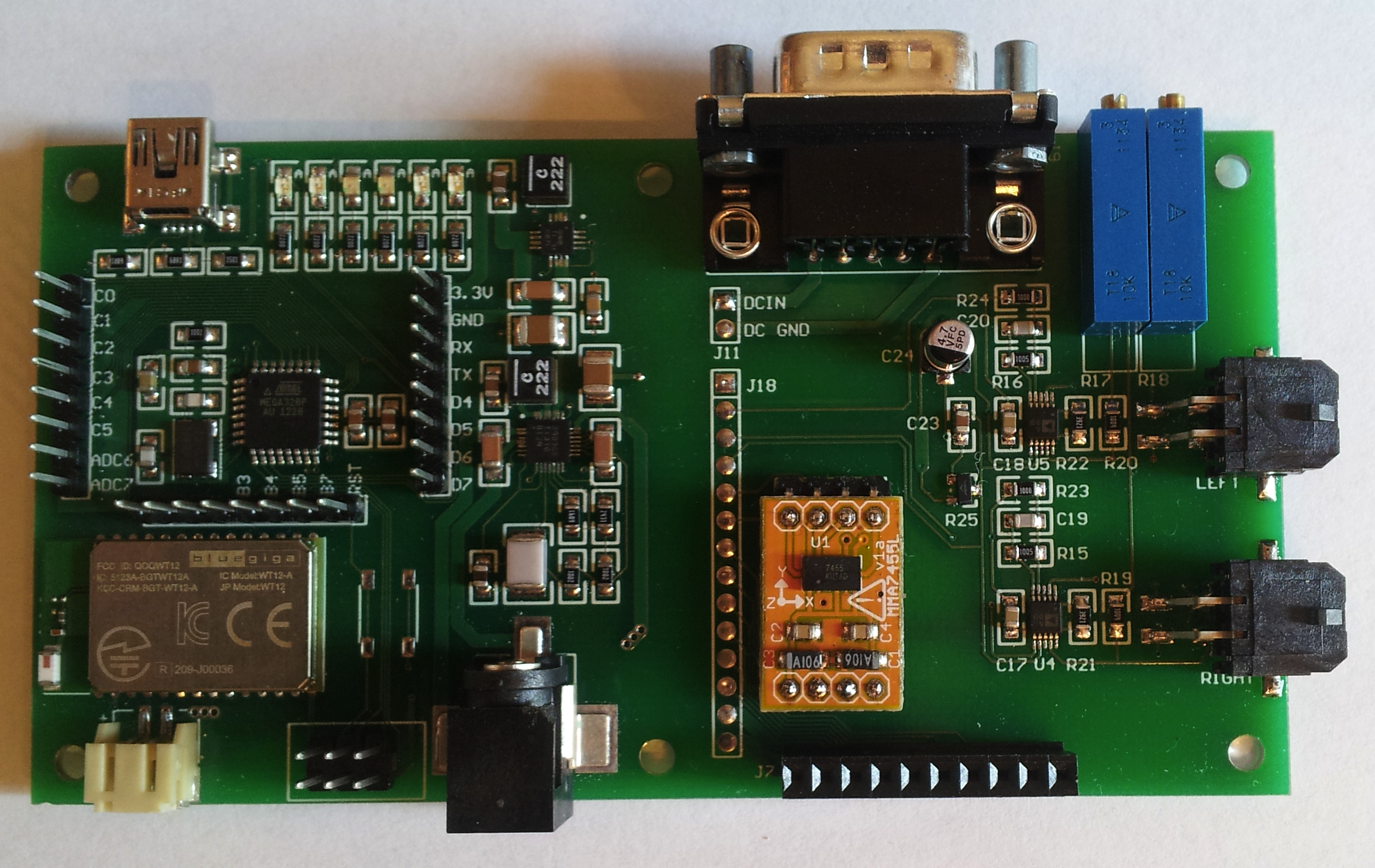
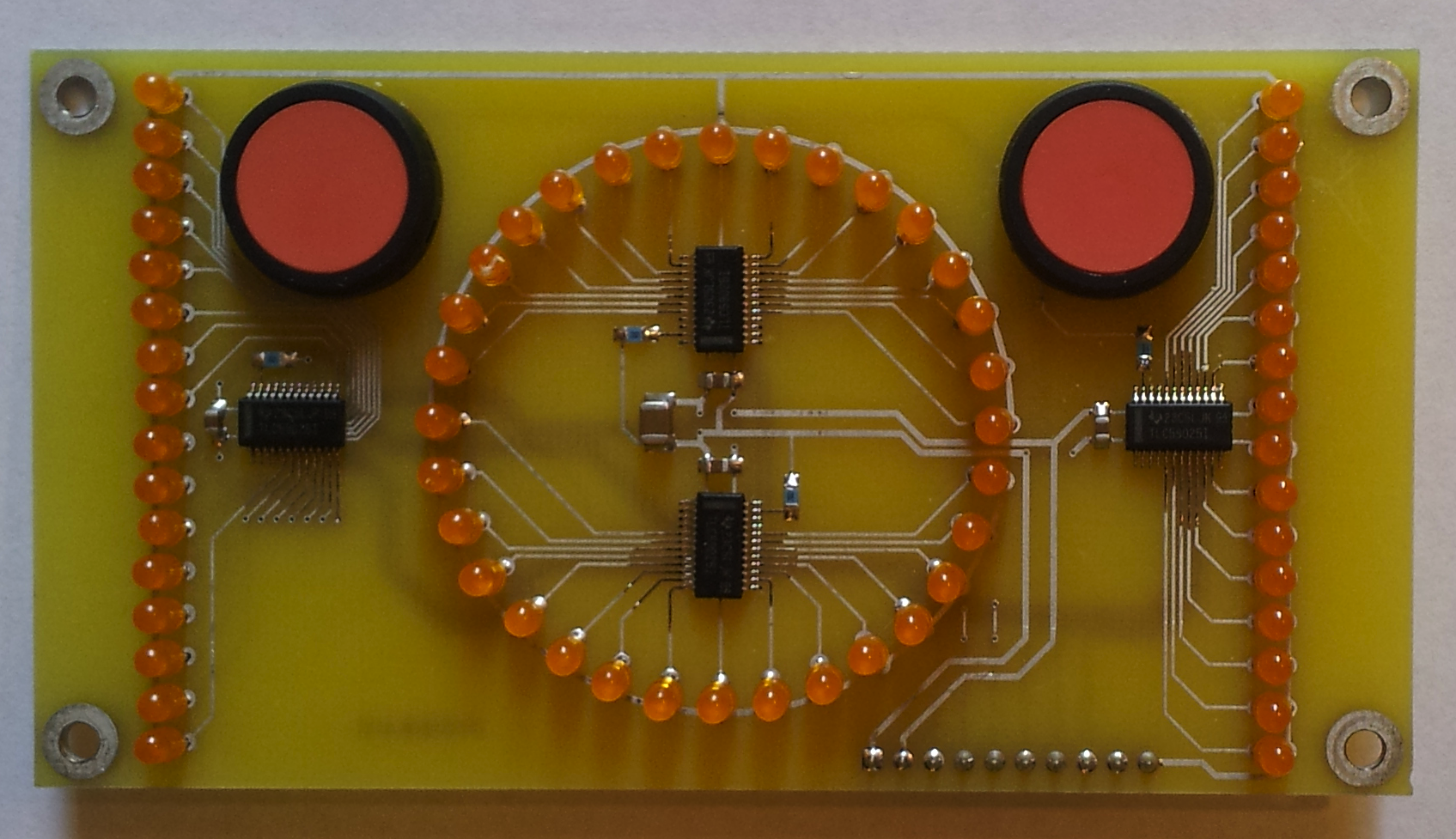
I also designed a second daughter PCB with LED indicators and a pair of pushbutton switches. The LEDs are used to provide a visual display the forces applied to each pedal and the computed heading. The pushbutton switches are used to put the device in ‘standby’ mode, reset the system, perform calibration, and initiate a USB bootloader for firmware changes.
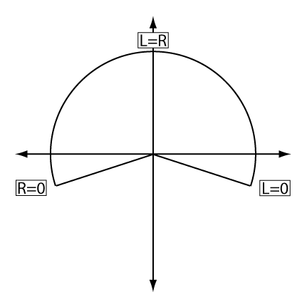
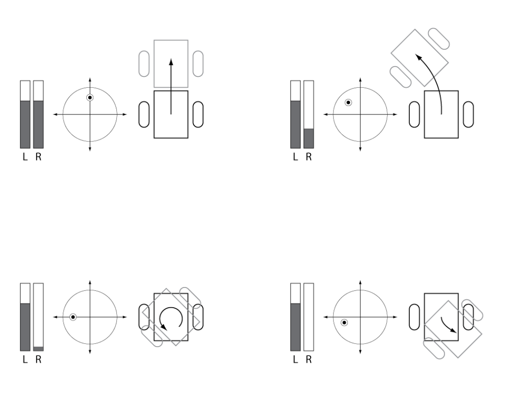
The wheelchair is driven using a virtual joystick who’s position is computed in polar coordinates from the combination of the forces applied to the pedals. The distance (speed) component is simply taken as the greater of the two forces. The angle (heading) component is computed from the balance of the forces applied to the pedals using the following equations:
\(\Large balance=\frac{L}{L+R} – \frac{R}{L+R}\)
\(\Large angle=\frac\pi2 + (balance \times range)\)
The result is an angle which is +/- range radians from the positive Y axis. I chose a range value of about 1.9 radians (109º).
The polar coordinates of the virtual joystick position are converted to cartesian (X/Y) coordinates and filtered using a second order lowpass filter with an fc of about 0.7 Hz, before being transmitted via serial interface to the SERDAC board mounted in the 1812 joystick housing. The lowpass filter corner frequency was chosen experimentally as the best compromise between responsiveness and smooth operation.
The 218º range of steering allows a center wheel drive wheelchair to not only rotate in place, but at the very extremes of the range it will actually make a turn while also moving in reverse. Although it is not possible to drive straight in reverse the user can still back out of a position using a ‘tacking’ type of motion. Obviously a 360º range of steering would be ideal but 218º seemed to be adequate, considering the challenges. My feeling is that a wider range of steering while providing more maneuverability also creates a less intuitive experience for the driver. At some point, once Alejandro has gained some level of mastery I may try further increasing the steering range if it seems advantageous.
Prior to each use, after Alejandro’s feet have been strapped into the pedals, a simple calibration must be performed to establish a baseline force while his toes are relaxed. When Alejandro is not intentionally applying any force to the pedals a button is pressed which stores the current values for each pedal. These values represent an offset and are subtracted from the continuously measured pedal values.
Thresholding with hysteresis is applied to the offset pedal values. This prevents small amounts of mechanical or electrical noise from causing the wheelchair to ‘creep’ while stopped. Additionally, while the current pedal values are below the threshold, the previously established offsets are very slowly adjusted to approach the current (below threshold) pedal values. This compensates for any long term mechanical or electrical drift in the system. In practice this technique has worked quite well.
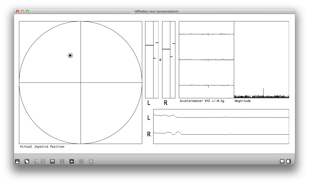
I also wrote a Max patch which monitors the system via bluetooth connection. This allows me to observe the sensor values in realtime while Alejandro operates the wheelchair and make adjustments to the control algorithm.
Success
So far the system has been working great and Alejandro has quickly been learning to drive his power wheelchair. His right foot is somewhat stronger than his left and at first he had a tendency to drive in circles, continually turning right. I was tempted to increase the sensitivity of the left pedal to compensate, but under advice from his physical therapist I resisted this temptation and eventually he has learned to compensate on his own and apply less pressure with his right foot in order to go straight.
It has been truly thrilling for us as parents to watch as Alejandro persistently works at learning to control his own movement in space. His motivation is amazing. For a kid like Alejandro there is nothing quite like finally being able to explore your environment all by yourself.

This work is licensed under a Creative Commons Attribution-ShareAlike 3.0 Unported License.
")
")

