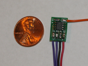
I wanted to find a switch that Alejandro could operate. We tried all of the most sensitive mechanical switches available to us but he wasn’t able to operate any of them. Alejandro can move his fingers but he isn’t able to apply any force to speak of. I knew that he would be able to operate a capacitive proximity sensor, since it only requires that he touch the sensor – no pressure is needed. I did some searching and did find a few assistive products, but they were all rather expensive. Furthermore they were all designed as remote switches, ie. they would operate a device (eg. electronic toy) that was connected remotely to the switch via wires. At Alejandro’s young age we felt that it would be better for him cognitively if the device that he operates is the same as the one that he touches, in order to better develop the cause/effect wiring in his little brain. Hence the birth of the Touch Switch.
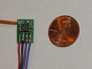
The Touch Switch is an extremely sensitive capacitive proximity sensor switch. It is a small two-sided circuit board, designed to be as small and cheap as possible so that it can easily be embedded in just about anything for modification (eg. electronic toy).
The Touch Switch works by detecting a change in capacitance between a sensing plate and ground. The sensing plate is just a conductor with a large surface area (eg. piece of metal foil). When the sensing plate is approached by a finger the capacitance rises and the switch is closed. When the finger is removed the capacitance drops and the switch is opened.
At the heart of the Touch Switch is the NXP PCF8883 integrated circuit. The circuit board measures 0.385″ x 0.555″ and operates from a 3-9 volt DC power source which makes it perfect for modifying most toys. Connected to the circuit board are five wires:
| Wire | Terminal | Description |
| RED | V+ | 3-9 volts DC |
| BLACK | GND | GND |
| VIOLET | SW | normally open switch contact |
| VIOLET | SW | normally open switch contact |
| ORANGE | TOUCH | touch sensor input |
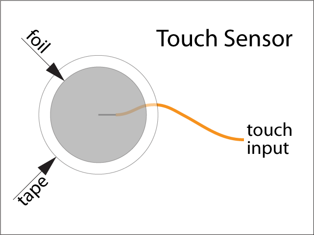
The orange wire is connected to a sensing plate. In most circumstances a 1″ diameter aluminum foil disc covered by clear cellophane tape works well as a sensor. Sensitivity is increased by increasing the area of the sensing plate. Placing a thin insulator (piece of tape) over the sensing plate also improves functionality by causing a more dramatic increase in capacitance when the sensor is actually touched. It is important to keep the length of the orange wire as short as possible. The range of capacitance that the touch sensor can measure is limited. If the orange wire is too long then the baseline capacitance will be too high and the Touch Switch will not function properly. A sensing plate that is too large will have the same effect. The length of the orange wire should be less than a few inches.
When the Touch Switch is triggered the two violet wires are connected together by the circuit using a solid state relay. The violet wires should be connected across the terminals of the device’s switch/pushbutton whose function is being made accessible. The maximum current handling of the relay is 200mA, which is plenty for most electronic toys that play music, make sounds and flash lights. It may be not suitable for toys that use large batteries (eg. C or D cells) and have motors. If the relay chip is switching too much current it will get hot and eventually burn out.
The red and black wires are connected so that the Touch Switch receives power when the device it is being used to modify is powered on. This should be between 3 and 9 volts DC. The Touch Switch circuit constantly auto-calibrates its baseline capacitance measurement. When power is first applied it may take a few seconds for it to establish proper calibration.
NOTE: I have found that toys that use a pair of 1.5V batteries (eg. AA) may not work reliably as the batteries begin to drain. For reliable operation the Touch Switch power supply must remain above 3V. Toys that use 3-6 1.5V batteries work best.
Circuit Documentation
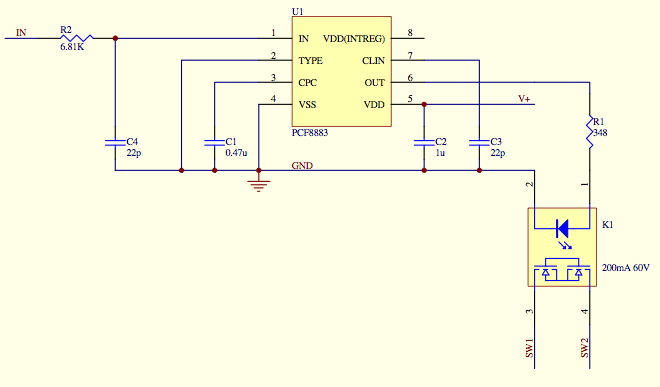
Here is the schematic:
Here is the Bill of Materials with part numbers from Mouser Electronics.
| Designator | Part Type | Manufacturer Part# | Mouser Part# | Mouser USD |
| C1 | 0.47u | CGJ4J2X7R0J474K | 810-CGJ4J2X7R0J474K | $0.15 |
| C2 | 1u | CGJ4J2X7R1C105K | 810-CGJ4J2X7R1C105K | $0.16 |
| R2 | 6.81K | CRCW08056K81FKEA | 71-CRCW0805-6.81K-E3 | $0.08 |
| C4 | 22p | GRM21A5C2E220JW01D | 81-GRM21A5C2E220JW1D | $0.42 |
| C3 | 22p | GRM21A5C2E220JW01D | 81-GRM21A5C2E220JW1D | $0.42 |
| K1 | 200mA 60V | ASSR-1218-003E | 630-ASSR-1218-003E | $1.78 |
| R1 | 348 | CRCW0805348RFKEA | 71-CRCW0805-348-E3 | $0.08 |
| U1 | PCF8883 | PCF8883T/1,118 | 771-PCF8883T1,118 | $2.48 |
Here are the Gerber files and NC drill for the circuit board:


Wow great job, waiting for a kid to wait to be 5 years old before assisting him is ludicrice. You are an inspiration to all of us who roll about to get where we want. I can see a lot of years of making more adjustments, but I know you will pecevere. There is no way today of knowing the potential of this little guy. But if his dad is any example, get out of his way.
Hi! That’s a real great work that you’ve done!! Congratulations. Over 20 years ago, i did some electronics at school. Today i work in a disabled home as a handyman. many doors are sliding doors driven by a motor. The push buttons to open the doors are very unhandy for many of the disabled wheelchair people. So i thought a touch switch would be nice, i would glue a metal foil on the door frame so that they just need to touch it to open the doors. This smd circuit, did you hack a toy to get it or buy it? Do you know any way how to get this kind of circuit with a relay to simulate the push buttons? Any tip is welcome.
Best regards and greatings from a little country called Luxemburg in the middle of europe.
Hello Marcel. I built and repaired doors for 18 years. Location of activation switches is to ADA standards and spec’d by the Architect. On existing buildings I had to follow standards as to height, distance to door and type of pushplate. Often, multiple plates are useful. The “Open time delay” adjustment of the door operator must be adjusted to hold the door open long enough for the person to move through. A Threshold sensing device holds the door open as long as there is something there. Radio remote controls from wheelchairs are popular. Here is a link to door info from AAADM. If you need help, contact them and they will advise you and recommend a local Technician to straighten things out.http://www.aaadm.com/pdfs/SwingDoorOM0210.pdf
Hi Marcel,
I don’t currently have any of the circuit boards left, more would need to be manufactured using the CAM files that are posted, however…
Since I originally posted this I’ve discovered this circuit board which does the same and is easily obtainable for cheap:
http://www.adafruit.com/products/1374#Description
If you click on ‘distributors’ you’ll see that there are several in the EU.
The output current is rather low and so you would need to use a transistor to drive a relay coil, but it shouldn’t be too difficult. Here is one example of how to do so:
http://mbed.org/users/4180_1/notebook/relays1/
I hope that helps!